If developing electronic components, hardware or devices has been one of your dreams, then you are in the right place. In this post, you will be introduced to a simple Arduino project using the Arduino Uno board.
This beginner project is focused on building a countdown timer using an Arduino Uno and a couple of components that will be introduced to you. The development of a countdown timer is a great way to get started and the next steps will show why.
Basic Arduino countdown timer
Parts needed
- Arduino Uno Board – This is the microcontroller board based on the ATmega 3284.
- Potentiometer – This are three-terminal resistors that serves as an adjustable voltage divider. The potentiometer will be used to tune the contrast of the LCD. You may need to fiddle with it a bit in order to see it display something on the screen.
- LCD display – This is a back light Display that shows the number on the countdown. The LCD features a 16 X 2 character display which means it can display up to sixteen characters on each of its two lines.
- Half-size breadboard – This is the construction base that supports the components you will use throughout the project.
- Jumper wire pack
- Header strip
The Steps
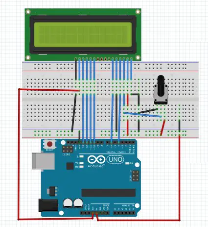
The complete breadboard layout can be seen with the connections needed to accomplish the building of the countdown timer. The schematic diagram also helps you read the connections for the project. These diagrams have been provided to assist you with understanding which components go where and for verification purposes. You can learn more about the wiring process for each component here.
4 pins of the LCD will be left unused. (you can find the data sheet of this LCD here)
The LCD is basically a parallel port LCD featuring 16 X 2 character display meaning we could display up to 16 characters on each of the two lines.
The following diagram will help you read connections more easily, but if you feel more comfortable with the one above, the following can still help to verify your wiring.
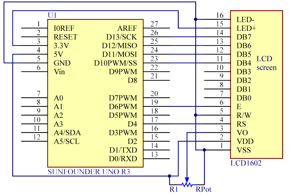
source: sunfounder.com
In this project, the potentiometer serves to tune the contrast of the LCD. You might need to play with it a little to see anything appearing on the screen. A common mistake is to have it totally turned down, and having the illusion the connections have not been made correctly.
You can find out more about the wiring process here.
Sketch (The code)
The code explained
 lcd.setCursor(1,0);
lcd.print("tutorial45.com");
The line above sets the writing head to the position 1,0 and prints tutorial45.com from that position.
 lcd.setCursor(6,1);
lcd.print(":");
This sets the writing head to the position 6,1 and prints :
 lcd.setCursor(9,1);
lcd.print(":");
This sets the writing head to the position 9,1 and prints :
The following picture perfectly illustrates what the above lines do.

The other lines in the code work with the same principle but in this case, the words become countdown numbers. The six cells will show the hours, minutes, and seconds as the timer counts down. The timer changes under set conditions determined by the multiple ‘if’ conditions you can see on the code outlined above. A delay of 1000 ms in every iteration has been given. This is due to ‘zero second’ execution time for every other line in the loop.
The countdown timer built here starts from 23 hours, 59 minutes, and 59 seconds. It starts from this point and counts down to zero and starts over again. The starting point of the countdown timer can also be changed by inputting the value you want as H, M, and S in the sketch code. This allows you countdown from wherever you choose.