If you are reading this, you already know what a circuit board is and may have used one. But for those who don’t, here is a little introduction. A circuit board is a standalone board that mechanically supports and electrically connects electronic components using conductive tracks. Therefore, they form the bedrock of every electronic device or hardware. And as with every important electronic component, multiple types of circuit boards do exist. These circuit boards are sometimes specially designed to fit into different types of devices.
In this post, the different types of circuit boards available to you will be covered in details. And they include the following options:
- Breadboard
- Strip Board
- Printed Circuit Board
Breadboard
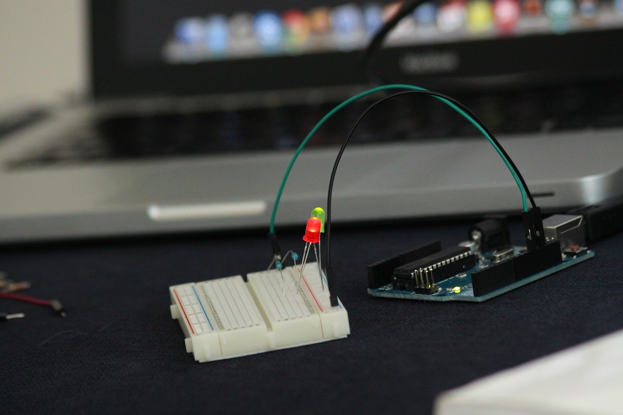
The first circuit boards in this list are bread boards. These types of circuit boards have earned the reputation of being great tools for prototyping. Therefore, they are commonly used by students and DIYers interested in electronics. The reason behind the popularity of breadboards in experimenting is due to the fact that you do not need to solder any components when working with a breadboard. All the components in a breadboard circuit can therefore be reused in other projects.
Although the specifications of different breadboards may vary, the design remains the same. A breadboard consists of a perforated block of plastic with metal spring clips under the perforation. These spring clips are generally made from nickel silver or bronze and they form the contact points that support electronic components. These metal strips also play the important role of connecting pins on the breadboard. And the layout of a breadboard generally consists of two distinct areas namely: terminal strips and bus strips.
Terminal strips form the main area of the circuit board. This is where your electronic components will be located or placed when prototyping. In this area, a notch marking the center line of the terminal strip area can be found. On each side of the notch are tagged rows marked with letters. Both sides of the notch are also interconnected using a radial pattern. As for the bus strip, it serves as the power resource of the breadboard. This means it basically introduces power to the entire circuit. The average bus strip also consists of two rows. One row serves as ground and one serves as the supply voltage.
Finally, jumper wires connect the entire structure on the circuit board together. These wires van be used according to color codes or your peculiar requirements. Solder-less circuit boards are great resources for prototyping and simple circuits but they have their limitations. These limitations include the following:
- Solder-less breadboards are limited to operating at lower frequencies. This is due to a larger capacitance and high Inductance of some of its connections.
- The average breadboard cannot naturally accommodate surface mount components without a grid spacing of 0.1 inches. A PCB breakout will be required.
- Breadboards are not built to inherently execute complex circuit designs or projects.
Despite the limitations associated with breadboards, the advantages it offers the user makes it a great option for prototyping. Breadboard components are relatively cheap and can be reused at will.
Stripboard Circuit Boards
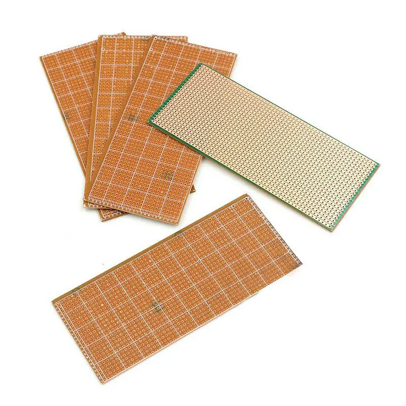
Stripboard or Veroboards, as they are called in the UK, are another option you can consider when creating circuit boards for your electronics project. These boards are great for prototyping and producing functional circuit boards for actual use. They are characterized by 0.1 inch rectangular grid holes, and parallel strips of copper on one side of the Stripboard. Unlike a breadboard, you will need to practice on your soldering technique as electrical components must be soldered onto them. With a 0.1 inch hole, you will also require components with 0.1 inch pins for the Stripboard.
The components you are most likely to use are DIP integrated circuits, connectors and other components with 0.1 inch pins. These components are always placed at one side of the board while their leads protrude at the other end. The leads must then be soldered. The soldering orientation must ensure leads are connected to the copper tracks at the other side of the Stripboard. In cases where you need to connect wires, 0.1 inch wires are recommended. Wires with this dimension can pass through holes and be soldered at the other side.
Stripboards are great for building small circuits and can also be adapted to have more holes for complex projects. Also, the needs to accomplish more complex circuit designs have led to variations of the standard Stripboard. These variations include: the Tripad and perf+. The TriPad is a Stripboard with broken or sectionalized conductive tracks. Each broken track spans three holes and supports the linking of multiple components. As for the perf+ variation, all its holes are not connected in a strip but are also connected to the bus. This is why perf+ boards are also called selective Stripboards. Although Stripboards and its variations are great for prototyping, some limitations exist. These limitations include:
- Stripboards with large number of holes can be confusing to build.
- They are not the best option for executing complex circuit designs
Wire Wrap Circuit Boards
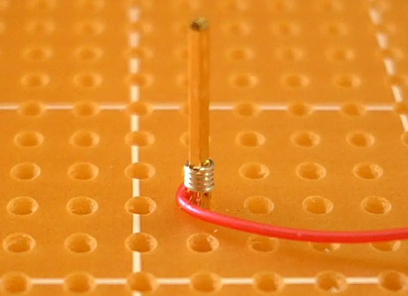
Wire wraps were initially developed to cater for telephone lines and the successes recorded led to its adaption for circuit board designs. This is why we have the option of working with a wire wrap circuit board to take advantage of the benefits it offers. A wire wrap consists of a board with sockets mounted on it. The sockets and components the board supports are connected through several layers of wires wrapped around the components, sockets and terminals. These wires can be either wrapped by hand or machine making it a solder-less circuit board.
Despite the relative obscurity surrounding wire wrap circuit boards, they are actually very reliable and can be used for complex applications. This is due to the fact that wire wrap connections are not affected by vibrations unlike soldered or breadboard connections. The lack of soldering elements also means that they are less prone to corrosion and have lower electrical resistance.
In terms of application, wire wrap circuit boards are used industrially in microwave circuits and in super computers. But despite the positives, wire wrap circuit boards are more expensive options than the others listed here. Also, prototyping tasks are easier to accomplish using other circuit board options than wire wraps.
Printed Circuit Boards
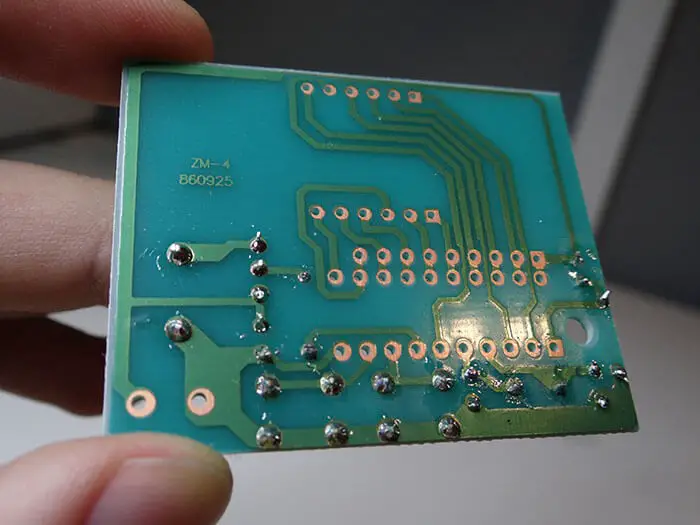
The most commonly used circuit board type in today’s fast-paced world is the printed circuit board (PCB). Its accommodating nature, design flexibility, and ease of use makes it the option of choice for most electrical engineers, manufacturers, and hobbyists. This is why tens of PCB design software and tools exist. A PCB consists of connecting copper tracks etched on a board. The electrical components are then soldered onto the tracks on the board according to the schematic design.
PCBs are currently used in every electronic device due to their ability to integrate both complex and simpler designs. Now, is probably the time to state that there are different types of PCBs and each type is best suited to meet your peculiar needs. The different types include:
- Single Sided PCBs –These PCB are tagged as single sided because they have just one layer of base material or substrate is coated on the board. This means that all the electrical components used will be soldered on that single surface. Single sided boards are built for use in simple electronics and are also great for prototyping tasks. Their relative affordable prices make them one of the common circuit boards used by students and hobbyists.
- Double Sided PCBs – A double sided PCB has two copper layers on both sides of one substrate layer. Holes are drilled on the board and they allow circuits on each side to be connected. Electrical components on double sided PCBs can be mounted using the through-hole or surface mount technology. Through-hole means the component’s lead is passed through a hole and soldering the end to the surface. Surface mount involves mounting the component and soldering to the board. This type of PCB is the most common type used by students and hobbyists.
- Rigid PCBs – A rigid PCB is basically a circuit board that incorporates fiberglass. The integration of fiber glass ensures that the PCB does not twist or get deformed when applied. Rigid PCBs are usually used in electronic devices that experiences regular use of have moving components situated around them.
- Flex PCBs – These types of PCBs make use of a flexible boards or plastic as their base. The ability of these PCBs to twist play an important role in certain electronic devices were flexibility is needed. Flex boards also come in single, double sided, and multi-layer format.
- Rigid-Flex PCBs – These types of PCBs integrate both the rigid and flexible formats earlier discussed. A rigid-flex PCB simultaneously consists of a rigid board attached to a flexible board to form the complete circuit.
Conclusion
Circuit boards are an integral part of every electronic device and they currently play an important role in the IoT and smart revolution currently taking the world by storm. At PCBWay, we understand the importance of each circuit board type and can help you with your prototyping needs. Outsourcing your circuit board prototyping task is the best way to ensure you take advantage of the benefits each circuit board has to offer.