The saying ‘practice makes perfect’ is one that rings true in the electronics and hardware manufacturing niche. Therefore, to elevate your soldering, PCB design, and creativity, taking on DIY projects on a regular basis is recommended. So, here is a slightly more advanced DIY electronics project you can undertake. The project is the development of a digital wristwatch using the digital watch electronic kit that can be purchased here.
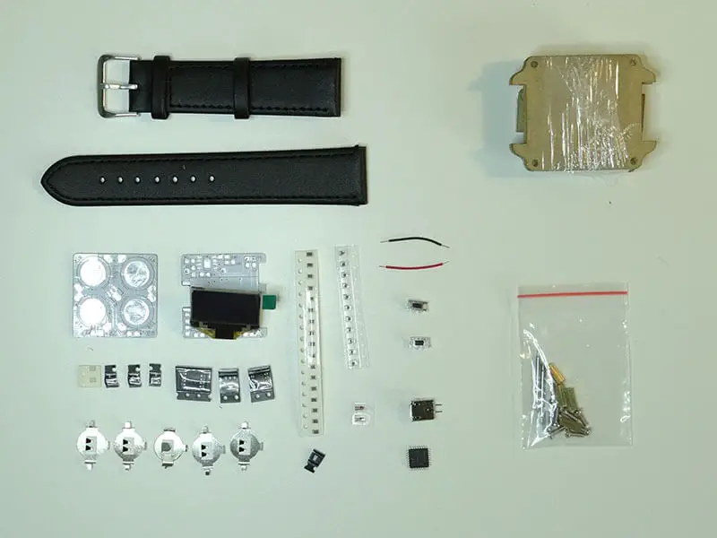
The project is geared towards more experienced DIYers who already have some experiences with soldering components onto a PCB board. This is because you will be working with small surface mounted components and an even smaller PCB board. These components may be smaller than you are used to but with the instructions provided here, you will be able to execute the digital watch project in time. Now, the equipment in the kit, which is what is required, are:
- A microcontroller – for computing the details and activities of the digital watch.
- Diodes
- Integrated circuits
- Resistors
- Capacitors
- The LED screen
- Switches
- Battery mounts
- Cables or wires
- Watch casing and leather strap.
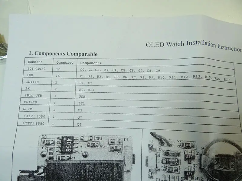
It is important to note that each component is listed in the user guide that comes with the kit. Other instructions that will prove useful to you are the instructions detailing were each component should be installed.
Steps to Producing the OLED Digital Watch
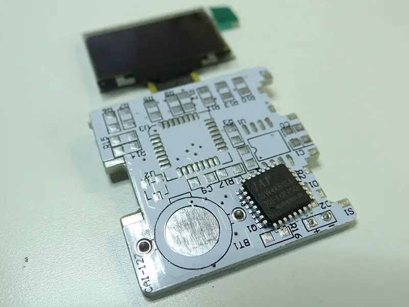
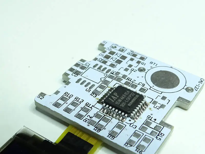
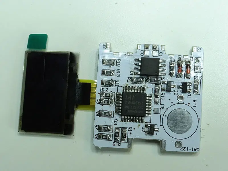
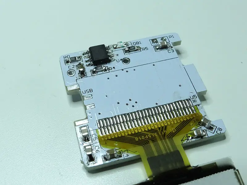
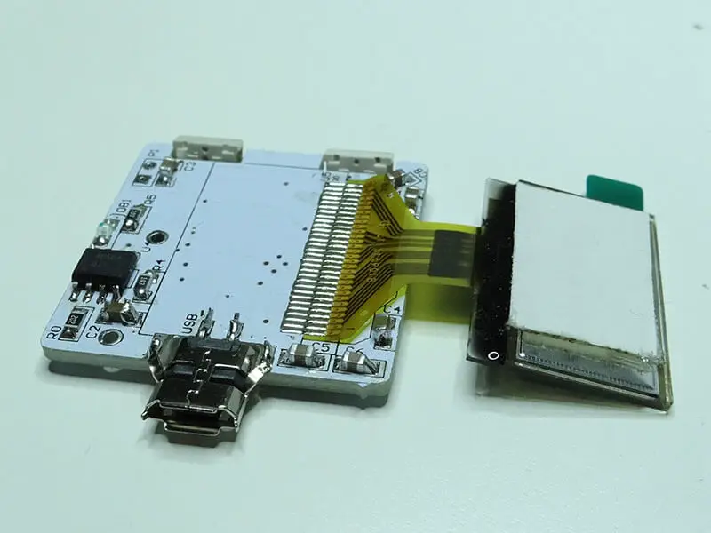
Step 1: Start the project by soldering the microcontroller. Begin by soldering just one of the microcontroller’s lead to the PCB. Next, check if all the other leads are properly aligned. If yes, ensure you solder the older leads and that there are no shorts.
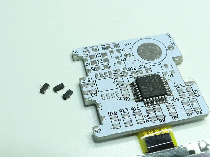
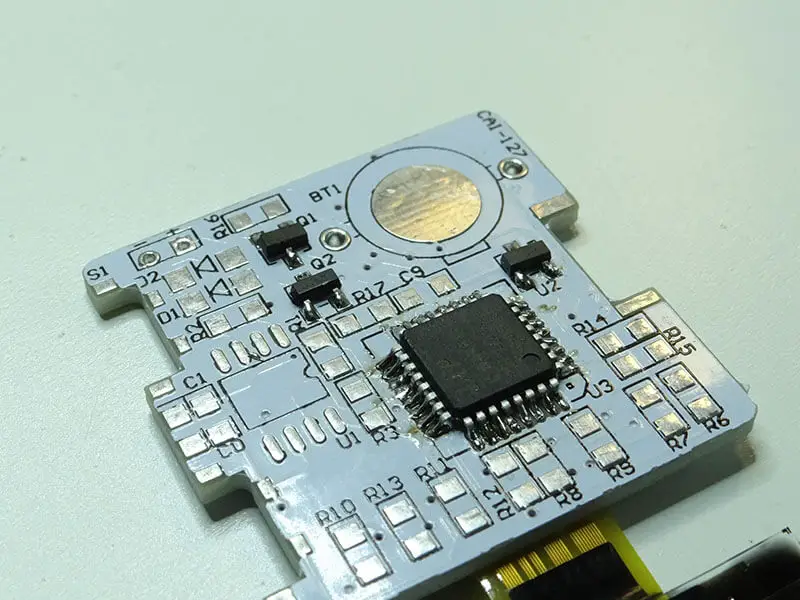
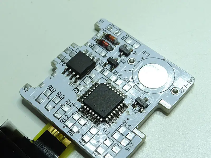
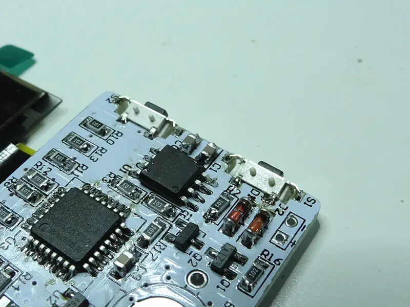
The next step is the installation of the three small integrated circuits ‘Q1, Q2, and U3’. Ensure they are properly placed and soldered as can be seen in the image below. Notice: each of them is different from the two others. Their name is printed on the package.
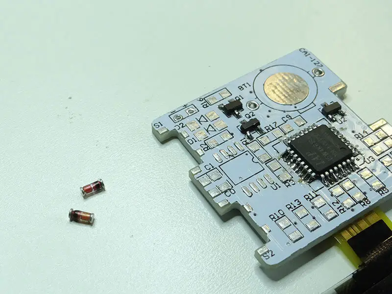
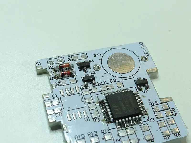
Step 2: Solder the diodes were ‘D1 and D2’ are visible. These labeled parts were put to help you know where each component should go. When doing this, ensure that the black strip on the diode matches with the strip on the soldermask.
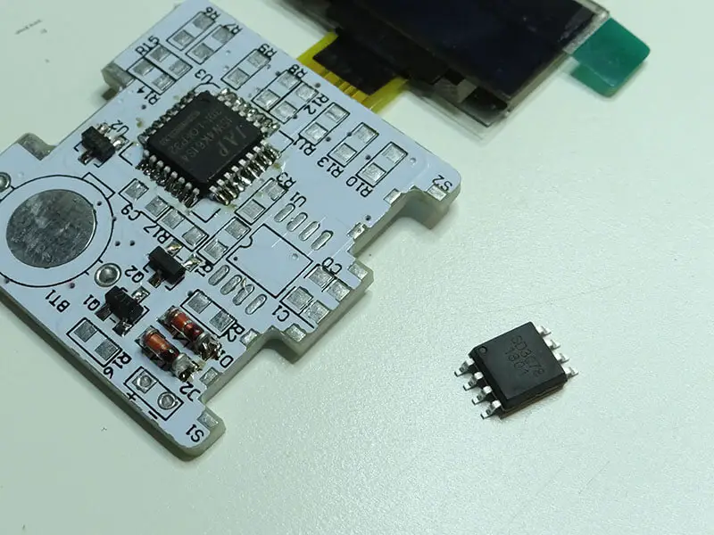
Step 3: The next component to solder is the integrated circuit (SD3078). With the IC, also solder one pin first, check if the others align, before going on to solder the other pins properly onto the PCB.
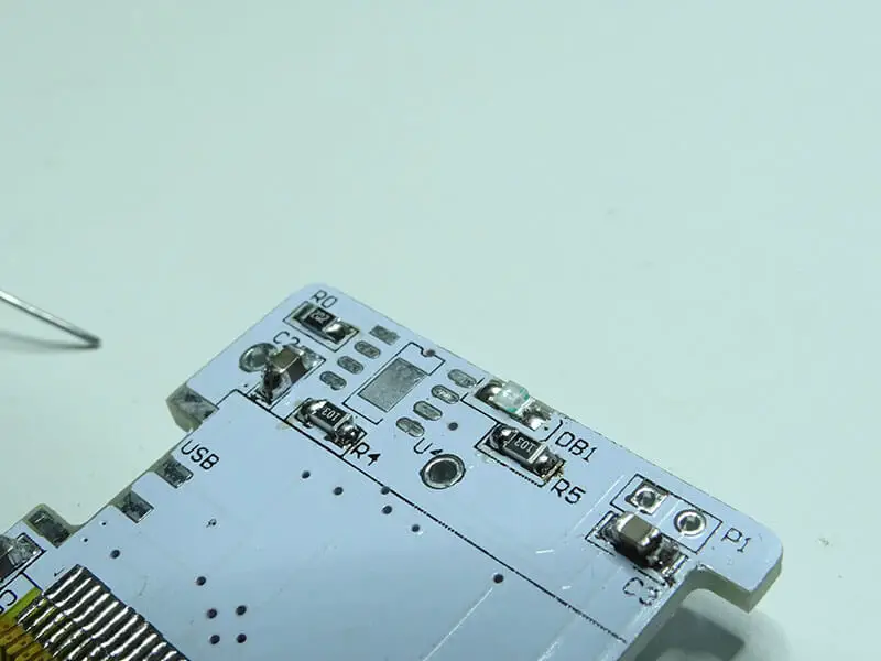
Step 4: The resistors should be soldered next. It is important that you ensure the correct resistor is soldered in its assigned place. Therefore, check the user guide attached to the kit before proceeding. The best way to go about the soldering task is to put a blob of soldering material on one pad and then solder the resistor on that side. Once this is done, you can then solder the other side. This is due to the fact that there will be resistors on both sides of the PCB.
Step 5: The capacitors should also be soldered in place according to the positions or spaces created for them. These spaces have been tagged ‘CX’ where ‘X’ is a number such as 1, 2, 3…
Step 6: Solder the smaller LED in place as specified in your table. This LED is named DB1 and a section on the PCB has been made for it.
Step 7: The last integrated circuit should be soldered into place once step six is done. To do this, also follow the instructions provided in step three.
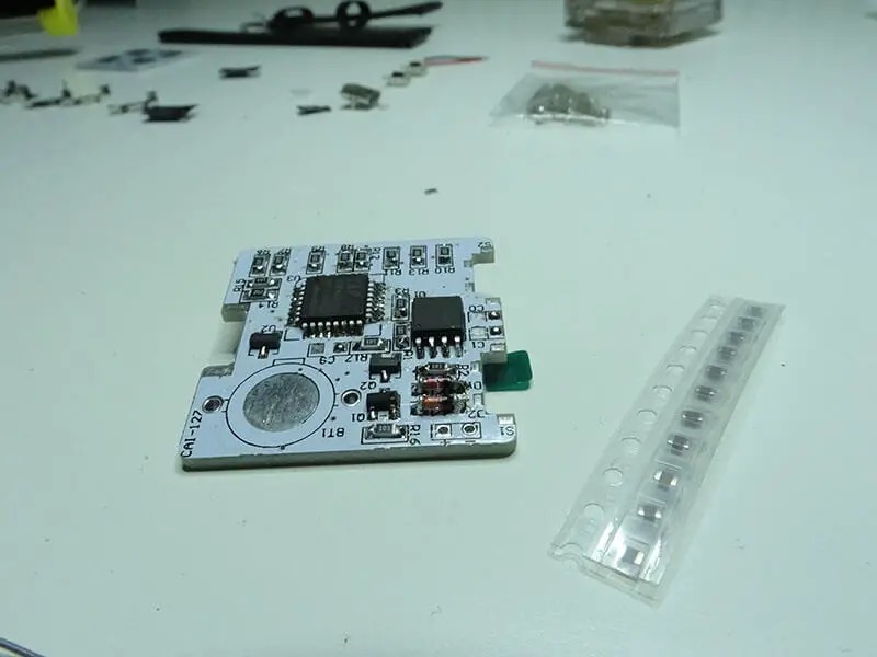
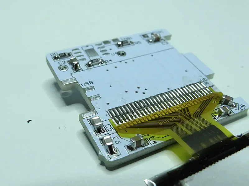
Step 8: Solder the small switches to the sides of the PCB. Ensure care is taken in order to do this right. Next, solder the USB connectors on the opposite side where the switches have been placed.
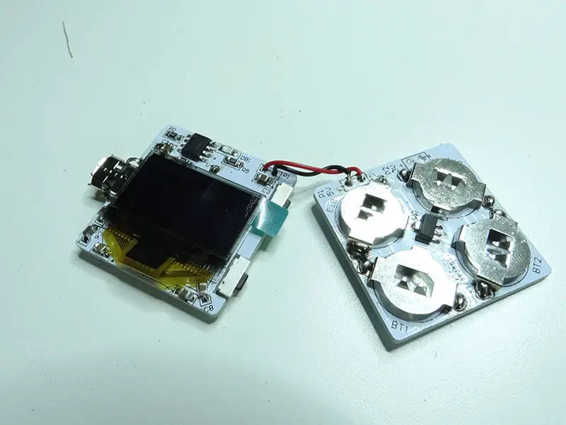
Step 9: The next step is soldering the battery mounts in place and attaching it to the PCB with the screens and components. Note that the battery mount using a through-hole mounting process should be mounted to the first PCB with the LED screen. While the other battery mounts equipped with surface mount technology should be mounted on the other PCB. Once this is done, you must connect both PCBs with cables. To do this, you will need to solder two cables at both ends of the PCBs.

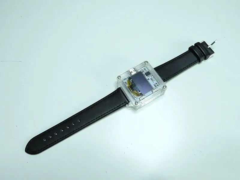
Step 10: Now, you can assemble the entire unit consisting of: PCBs, the acrylic case, and the leather straps. And there you have it, your own DIY OLED wrist watch built with Your Own Hands!
Conclusion
Note that everything you need to accomplish this DIY task is provided in the digital OLED wristwatch kit. The kit also includes a table of components and a user guide detailing where each component should go. Using these resources will get you showcasing your digital watch to family and friends in no time!